- Introduction
- Information Required to Draw a Classroom Using Two-Point Perspective
- Setting Up the Basic Frame for Two-Point Perspective
- Constructing the Front Wall
- Constructing the grid squares on the floor, walls, and ceiling
- Reflections on this session and plans for the next
- References
- Books that are easy for beginners to understand
- David Chelsea「Extreme Perspective! For Artists: Learn the Secrets of Curvilinear, Cylindrical, Fisheye, Isometric, and Other Amazing Drawing Systems that Will Make Your Drawings Pop Off the Page 」
- Robbie Lee「Perspective Made Easy: A Step-by-Step Guide」
- Scott Robertson「How to Draw: drawing and sketching objects and environments from your imagination」
- About the Japanese version of this article
- Books that are easy for beginners to understand
Introduction
Explanation in the video
The ‘Overview, Summary, or Conclusion’ of this article can be found at the beginning of the YouTube video, so please refer to it.
If possible, we would appreciate it if you could subscribe to our channel to help maintain the site. It serves as motivation for us!
Information Required to Draw a Classroom Using Two-Point Perspective
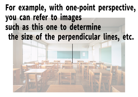
This step is the same as the one-point perspective method explained previously.
First, you need to understand the dimensions of the classroom.
In other words, you need to obtain floor plan information (actual measurements).
You can easily find this by searching on Google, so please look up the specifications of the classroom you want to construct.
In this lesson, we will assume a basic classroom and will not draw any details such as blackboards or windows.
We will only create a simple grid room.
Floor Information
Assume that the floor is 9 meters (29.53 feet or 354.33 inches) in depth and 7 meters (22.97 feet or 275.59 inches) in width.
Wall Information
Assume that the height of the walls is 3 meters (9.84 feet or 118.11 inches).
In this project, we will divide the floor, ceiling, and walls into 1-square-meter grids.
Note on Two-Point Perspective
For detailed knowledge of two-point perspective, please refer to videos from Lesson 5 or Lesson 6.
In this lesson, we will move forward with a simplified approach without explaining too much detail.
Setting Up the Basic Frame for Two-Point Perspective

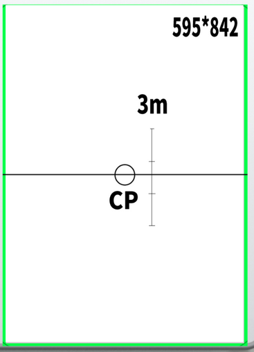
In this lesson, we will use a visual cone angle of 45 degrees and set the canvas size to 595×842 pixels.
You may use any canvas size you prefer.
If you are working with traditional tools, using an A4-size sheet of paper is perfectly fine.
A4 paper is 21 centimeters (8.27 inches or 0.69 feet) wide and 29.7 centimeters (11.69 inches or 0.97 feet) tall.
Other paper sizes are also acceptable.
You can simply use the values in centimeters and plug them into your calculations.
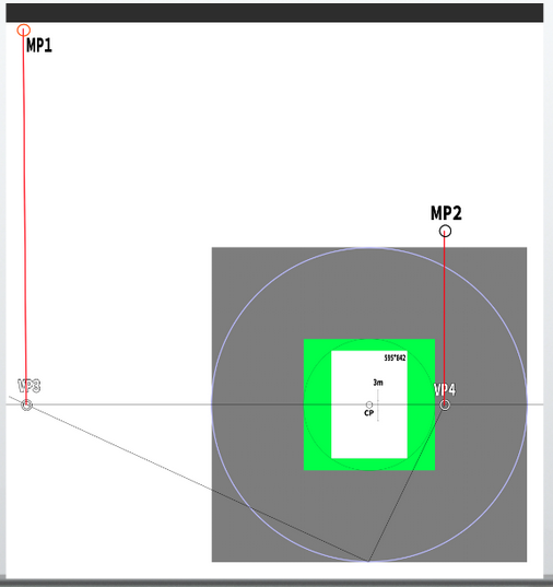
First, set the VPs (vanishing points)
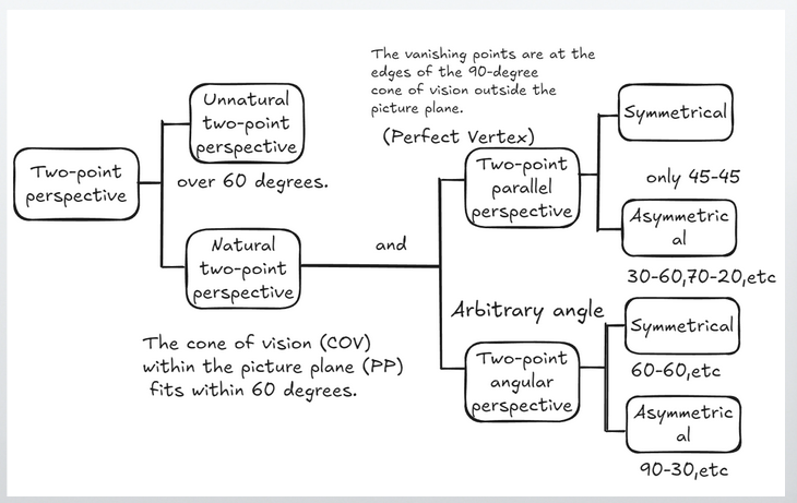
In this lesson, we will assume an asymmetrical two-point perspective setup, where the angles to the vanishing points are 65 degrees and 25 degrees.
・Assuming that the horizon line (HL) is at the center of the screen, where are the vanishing points (VPs) located?
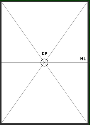
In one-point perspective, the VP is located at the center, so its position is easy to identify.
However, in order to determine the diagonal vanishing point (DP), you first need to decide the station point (SP).
This means you must decide how far the SP is from the center point (CP).
This is not a matter of finding a single correct answer but rather making an arbitrary choice based on your composition.
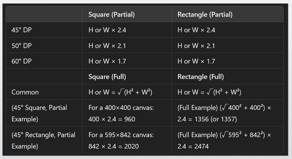
In this case, we assume that the entire screen (A4 size, printed paper) fits within a 45-degree visual cone.
Note: If we calculate the position of the vanishing points (VPs), we get the following result:
√(595² + 842²) × 2.4 ≈ 2474 pixels
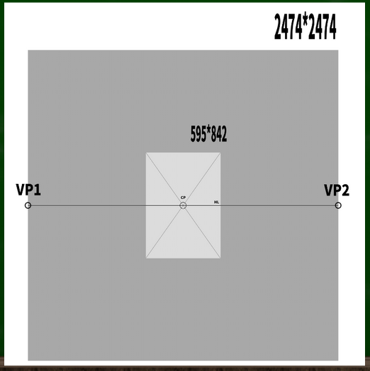
In other words, the two vanishing points (VPs) should be placed at these positions.
From the perspective of one-point perspective, these would be considered diagonal vanishing points (DPs).
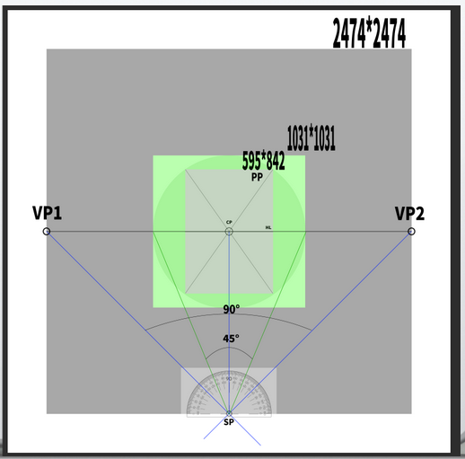
You can see that the picture plane (PP) fits within the 45-degree visual cone.
Note:For an explanation of why this is the case, please refer to the previous article.
Although this setup allows for two-point perspective, it is almost the same as the one-point perspective method from the previous lesson.
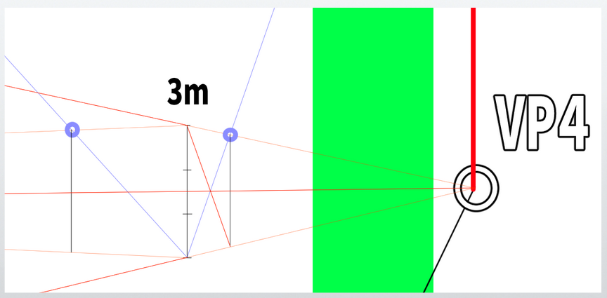
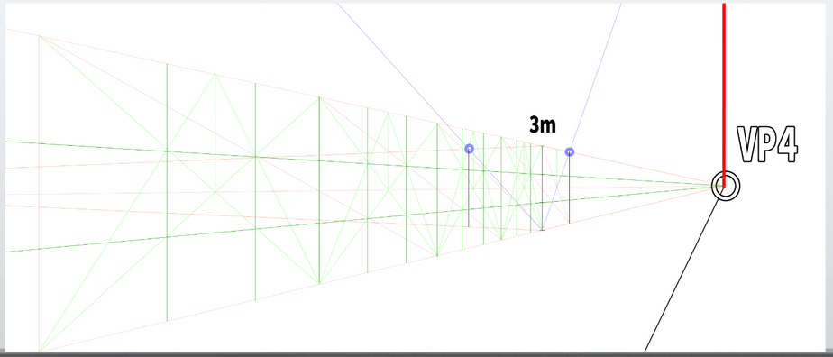
This time, we want to shift the left vanishing point (VP) by 20 degrees.
Currently, the VPs are located at 45 degrees to the left and 45 degrees to the right.
Therefore, we will change the angles to 65 degrees on the left and 25 degrees on the right.
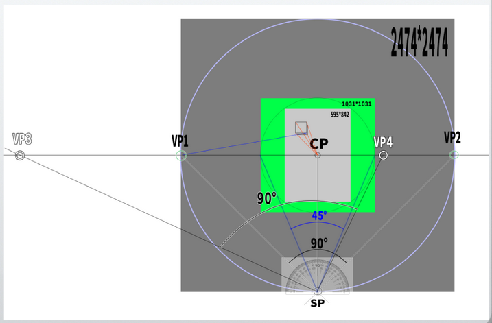
Changing the angle from the station point (SP) means that the positions of the vanishing points (VPs) will also change.
The newly created vanishing points will be labeled as VP3 and VP4.
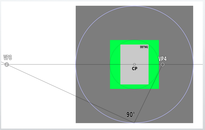
The screen has been simplified. This is the basic frame for this lesson.
Note:Detailed questions such as how the visual cone changes when the vanishing points move, or what happens to the center point (CP), will not be covered this time.
Constructing the Front Wall
First, draw an arbitrary perpendicular line.
In the previous lesson, the back wall was drawn too small, which made the floor space appear too large.
This time, we will draw the back wall a little larger.
(It will become clear later, but perhaps it would have been better to make it even slightly larger.)
If you have a rough sketch or reference image, use it as a guide to draw perpendicular lines.
Even a roughly drawn blackboard or similar object is enough, because one small item helps determine the overall scale.
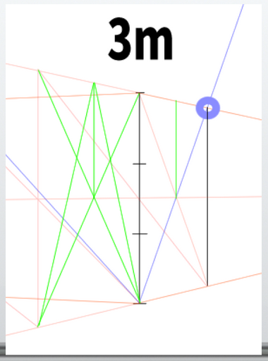
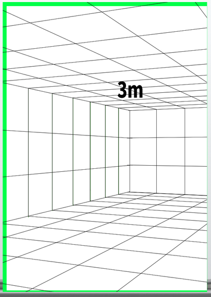
This time, draw a line representing a height of 3 meters (9.84 feet or 118.11 inches).
It is helpful to measure and divide the line using a ruler or similar tool.
The first perpendicular lines you draw should have the same proportions as the actual lines and should not converge.
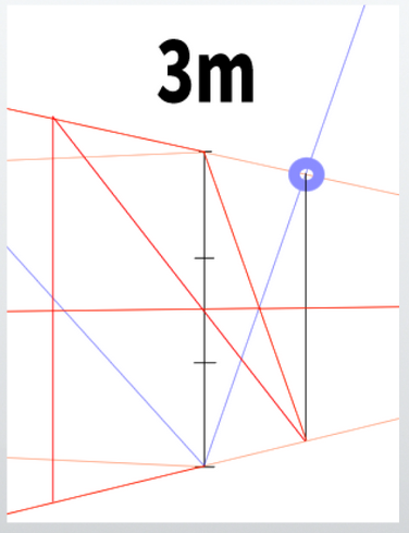
From this point, use the perpendicular line as a reference to construct a cube.
In other words, create a cube based on a 3-meter by 3-meter (9.84 feet by 9.84 feet) square plane.
This time, we will use the method of auxiliary lines.
For detailed steps, please refer to the previous article (Lesson 6).
The method involves extending lines from each vanishing point (VP) to the station point (SP) upward to find the measuring point (MP).
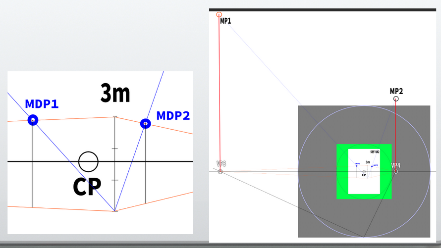
Using the line toward the measuring point (MP) as a guide, construct the cube.
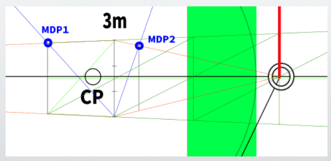
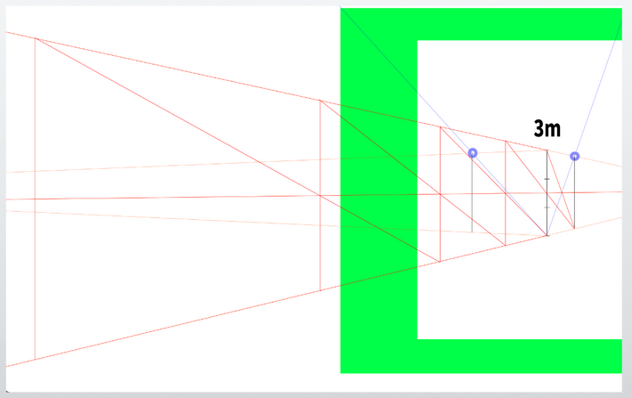
Duplicate this cube to the right and construct the front wall so that it measures 3 meters (9.84 feet or 118.11 inches) in height and 7 meters (22.97 feet or 275.59 inches) in width.
Use the diagonal division method that was used in the previous lesson.
The front wall of the classroom is 7 meters (22.97 feet or 275.59 inches) wide, so divide the farthest face into three equal parts to make it exactly 7 meters wide.
To divide it into three parts, use a triangle.
This is done by drawing a diagonal line that divides the rectangle in half, creating a triangle, which helps determine the positions for the three divisions.
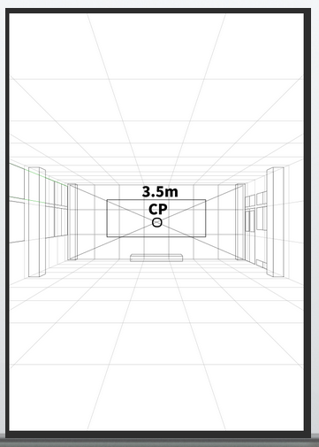
In one-point perspective, the center point (CP) was located at the center of the front wall.
In other words, it was exactly at the 3.5-meter (11.48 feet or 137.8 inches) position.
To find the 3.5-meter (11.48 feet or 137.8 inches) position in two-point perspective, divide the front wall into seven equal parts.
Use the same division method described earlier.
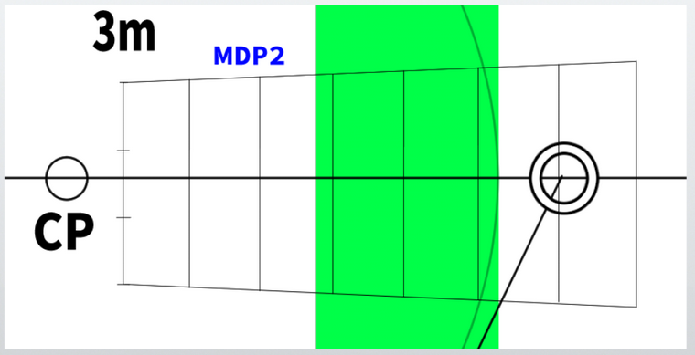
Simplifying it looks like this.

From here, find the 3.5-meter (11.48 feet or 137.8 inches) position by dividing the segment in half.
This position will be called CP2.
Note: Whether this is the exact center of vision in two-point perspective is left undecided.
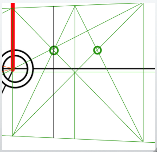
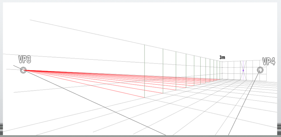
Constructing the grid squares on the floor, walls, and ceiling
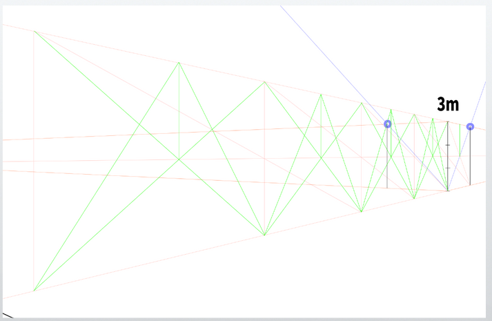
Duplicate the side face of the cube created at the beginning.
When duplicating, draw a diagonal on the face and draw lines from the edge toward that position.
This method is the same as the one used previously.
Continue dividing the face all the way to beyond the edge of the canvas.
Next, divide the side face you just drew into three parts.
As with the front face, use triangles to perform the division.
Perform the same operation on all side faces and divide each into three parts.
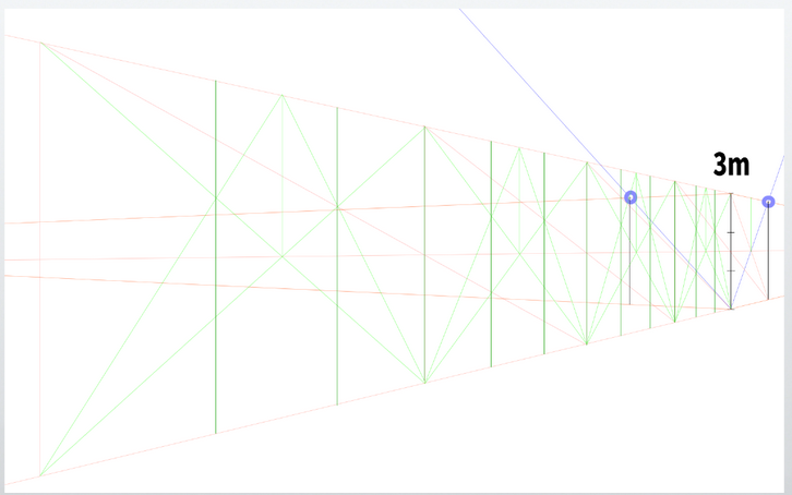
Using the three divisions as a guide, draw perpendicular lines for each.
Divide horizontally into three parts as well.
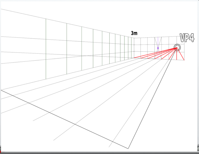
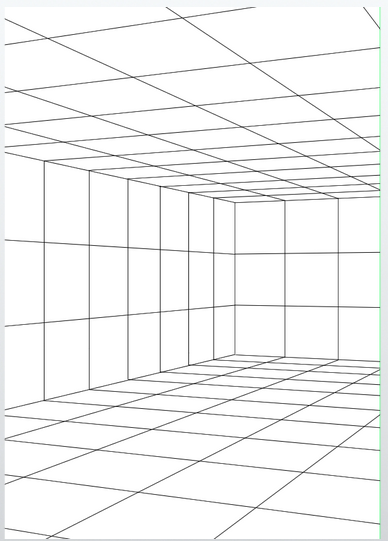
Extend the divisions onto the floor as well.
Extend the grid squares onto the floor as well.
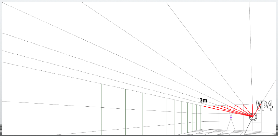
Extend the same grid squares onto the ceiling as well.
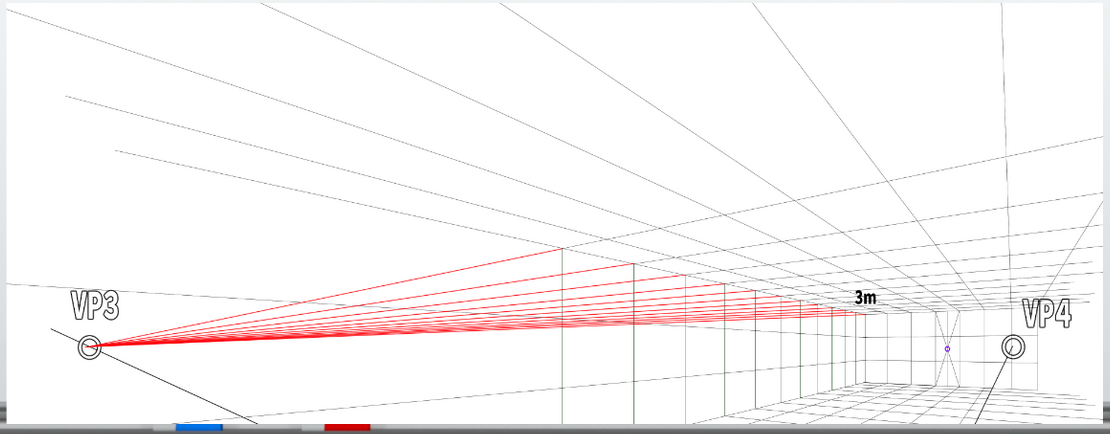
Extend the grid squares onto the ceiling as well.
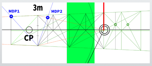
With this, the canvas is almost complete.
However, it is unfortunate that the floor slightly exceeds 10 grid squares.
If it had been made a little larger, it might have fit within 10 squares.
The completed drawing looks like this.
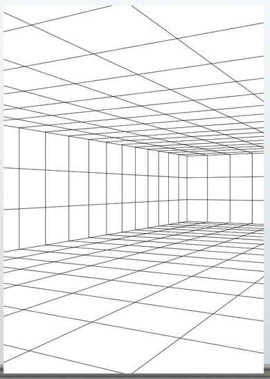
By the way, in the first take, it was far more than 10 squares.
Note: There is probably a method to estimate the number of grid squares on the floor from the initial perpendicular lines (for example, by preparing a floor plan), but for now, the goal is to learn the basic method of construction.
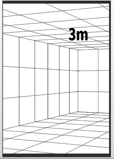
With digital tools, there is a method to forcibly fit the entire canvas by enlarging it.
Note: For example, by combining and enlarging the entire drawing area and fitting it into the original A4 size (595×842 pixels), it looks like this.
By doing so, the floor fits within 10 grid squares.
However, when enlarged, some lines may become rough.
Still, the base grid room is not used as the final classroom drawing but serves only as a sketch, guideline, and reference for drawing the main classroom, so having rough lines is not a problem.
Of course, in analog methods as well, you can import digitally or analog-drawn base drawings, enlarge them, and print them for use.
For example, printing in blue color can help prevent the base drawing from showing when used as a digital sketch.
Alternatively, tracing paper can be used to copy the drawing.
However, when drawing a classroom, it is usually faster to create the base using 3D or 2D software.
Drawing the base by hand each time is very laborious.
If you want to slightly change the angle, you have to start over from scratch.
Of course, this time the drawing was done with 2D software, but it was created without using most of the convenient perspective tools, assuming an analog method is possible.
In the future, I would like to introduce methods for creating detailed base materials separately, such as the convenient perspective features of Clip Studio Paint and Photoshop, or how to create grid rooms in Blender.
Reflections on this session and plans for the next
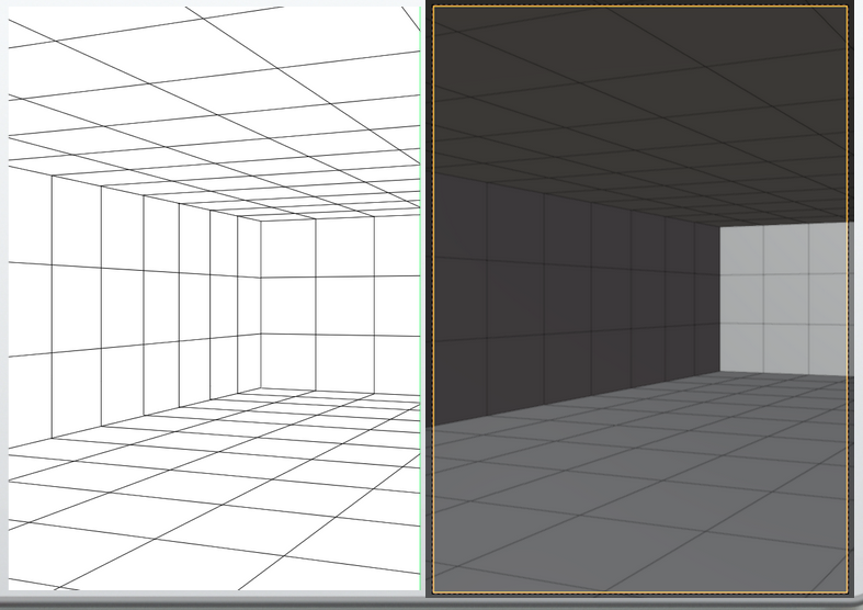
When approximated in Blender, the current canvas looks like this.
Simply changing the angle around the Z-axis by 20 degrees from the previous angle did not approximate the canvas well.
I do not fully understand the clear reason why it does not approximate well.
I have a rough grasp of it, but the reproduction method is somewhat complicated, so I need to deepen my understanding of Blender and perspective further.
Also, it is necessary to prepare floor plans and other measurements, align the units properly, and reflect them accurately.
In particular, it is necessary to deepen understanding of changes in the viewing frustum and the principal point when the field of view varies, and the settings of each.
For example, when rotating the camera or the head around the Z-axis, it is important to clarify the question of where the principal point will be.
This concludes the log for this session.
Next time, I plan to cover perspective related to circles (probably).
References
Books that are easy for beginners to understand
David Chelsea「Extreme Perspective! For Artists: Learn the Secrets of Curvilinear, Cylindrical, Fisheye, Isometric, and Other Amazing Drawing Systems that Will Make Your Drawings Pop Off the Page 」
The book contains many illustrations and is easy to understand. It also explains basic perspective terminology and provides a simple explanation of how to use perspective. However, it is important to note that the book focuses on ‘illustration (manga)’ rather than architectural perspective.
It is suitable as the first book to pick up for learning the basics of perspective in general.
Robbie Lee「Perspective Made Easy: A Step-by-Step Guide」
Robbie Lee「Perspective Made Easy: A Step-by-Step Guide」
This is a suitable book to pick up as the first one for learning the basics of perspective in general.
I found it to be simpler and more detailed than ‘Perspective! Learn Perspective Through Manga.’ Therefore, I especially recommend this book to beginners as their first read.
Scott Robertson「How to Draw: drawing and sketching objects and environments from your imagination」
Scott Robertson「How to Draw: drawing and sketching objects and environments from your imagination」
A book specialized in drawing, particularly focused on line art. Though somewhat complex, it provides a broad and in-depth explanation.
About the Japanese version of this article
This article is a translation of an article written in [https://souzoulog.com/2025/06/03/basic-of-perspective-10/]. For detailed references, please refer to this link.


Comments