- Introduction
- Information Needed to Draw a Classroom Using One-Point Perspective
- Setting Up the Basic Frame for One-Point Perspective
- Constructing the Front Wall
- Creating the Grid for the Floor, Walls, and Ceiling
- Placing the blackboard, teacher’s podium, windows, and columns
- 【Column】Imagining Classroom Perspective in 3D
- Next plan
- References
- Books that are easy for beginners to understand
- David Chelsea「Extreme Perspective! For Artists: Learn the Secrets of Curvilinear, Cylindrical, Fisheye, Isometric, and Other Amazing Drawing Systems that Will Make Your Drawings Pop Off the Page 」
- Robbie Lee「Perspective Made Easy: A Step-by-Step Guide」
- Scott Robertson「How to Draw: drawing and sketching objects and environments from your imagination」
- About the Japanese version of this article
- Books that are easy for beginners to understand
Introduction
Explanation in the video
The ‘Overview, Summary, or Conclusion’ of this article can be found at the beginning of the YouTube video, so please refer to it.
If possible, we would appreciate it if you could subscribe to our channel to help maintain the site. It serves as motivation for us!
Information Needed to Draw a Classroom Using One-Point Perspective
First, you need to understand the dimensions of the classroom.
In other words, you need to obtain information from a floor plan with real measurements.
You can find this by searching on Google, so start by looking for the layout of the classroom you want to design.
For this example, we will assume a basic classroom.
- We will assume that the floor is 9 meters (29 feet 6 inches) deep and 7 meters (23 feet) wide.
- The walls are assumed to be 3 meters (9 feet 10 inches) high.
- In this example, we will divide the floor, ceiling, and walls into 1-meter (3 feet 3 inches) square grids.
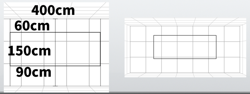
- The blackboard is assumed to be 1.5 meters (4 feet 11 inches) tall and 4 meters (13 feet 1 inch) wide.It will be placed with a 60-centimeter (2 feet) gap above it and a 90-centimeter (3 feet) gap below it.
- Other elements, such as fluorescent lights or windows, can be added if necessary.For now, we will only include the basic elements: the blackboard, columns, windows, and the teacher’s platform.
- For basic knowledge of one-point perspective, please refer to the second and third video lessons.
Setting Up the Basic Frame for One-Point Perspective
Prepare the canvas

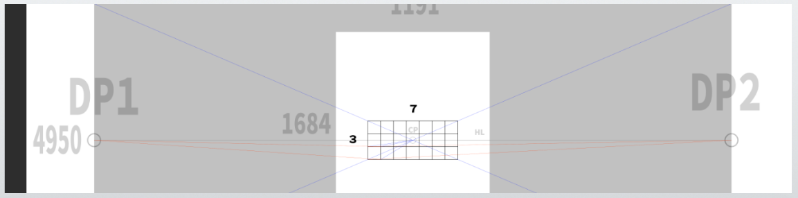
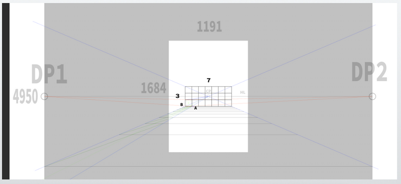
In this example, we will use a 45-degree cone of vision and set the canvas size to 1191 × 1684 pixels, which is relatively large.
The size of the canvas can be adjusted freely depending on your needs.
If you are working by hand, you can simply use an A4 sheet of paper, which measures 21 cm by 29.7 cm (about 8.3 by 11.7 inches).
You can calculate proportions by using the centimeter values as actual measurements.
For reference, 1191 × 1684 pixels corresponds to A4 size at 144 DPI (dots per inch).
At the more common resolution of 72 DPI, the A4 size would be 595 × 842 pixels.
In one-point perspective, the center of the screen usually represents the horizon line, which corresponds to the viewer’s eye level.
Of course, you can crop the image afterward to move the horizon line higher or lower than the center.
Eye level depends on the height of the observer, so it can be set freely.
In this case, for clarity, we will assume a person who is approximately 163 to 165 centimeters tall (about 5 feet 4 inches to 5 feet 5 inches), and we will set the eye level at 150 centimeters (about 4 feet 11 inches), which is half the height of the classroom.
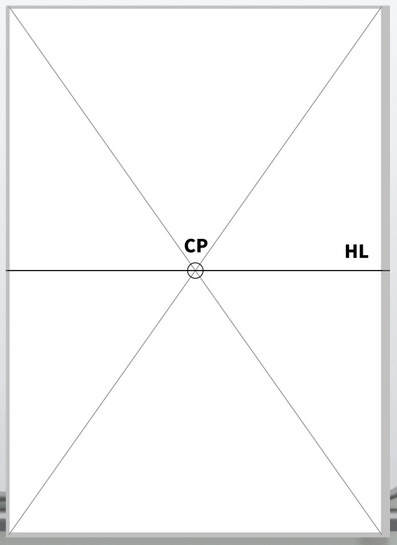
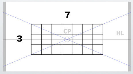
Use a ruler or draw diagonals on the paper to find the exact center of the canvas.
This center point is called the CP (Center of Projection), and the horizontal line drawn through it is the HL (Horizon Line).
With these two elements in place, the basic setup for one-point perspective is complete.
Set the vanishing point for the diagonal lines
Next, set the vanishing point for the diagonals.In this example, we assume the entire image fits within a 45-degree cone of vision.
For details about the cone of vision settings, please refer to the third video lesson.
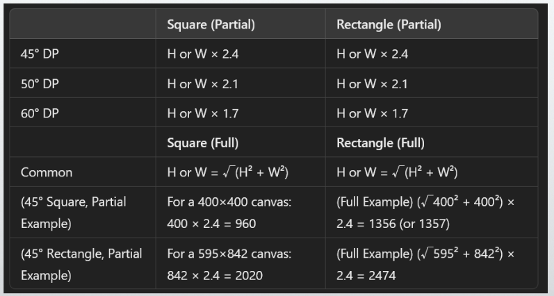
For this calculation:
X = √(1191² + 1684²) ≈ 2062
Then, 2062 × 2.4 ≈ 4950
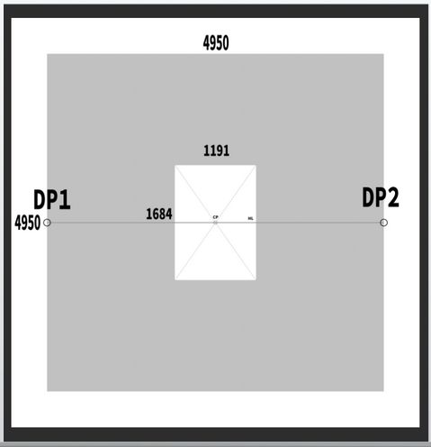
Set the diagonal vanishing point (DP) at the edge of a 4950 × 4950 pixel canvas.
For analog work, this can be difficult. You may need to prepare many sheets of paper or use string to help.
Alternatively, you can reduce the size by narrowing the cone of vision.
A rough estimate, such as how many A4 sheets laid side by side would cover the space, is also acceptable.
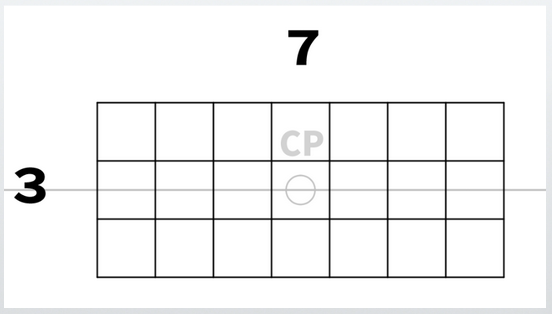
Constructing the Front Wall
Let’s start by considering the back wall, and then extend lines from there.
The back wall has no converging lines, so its proportions remain the same as the actual measurements.
(In other words, if you measure it with a ruler, the ratios will be identical.)

Draw a rectangle with any size, for example 3 units tall (vertical) by 7 units wide (horizontal).
If this size is small, you can draw more of the floor and ceiling.
For this example, we chose this size, though looking back, it might have been better to make it a little larger.
Create a grid of 1 square centimeter (approximately 0.39 square inches) cells.
Note: This is not the actual size, but a matter of proportion.
Whether the real size is 1 millimeter or 1 kilometer, one side is assumed to be 1 centimeter (about 0.39 inches) for this drawing.
Therefore, the actual length can be freely decided as long as the proportions are maintained.
Creating the Grid for the Floor, Walls, and Ceiling
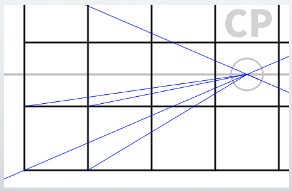
From the corners of the front wall you just created, draw lines extending toward the center of projection (CP).
From here, the work becomes a bit more detailed.
Using the diagonal vanishing point (DP), construct 1-meter (about 3 feet 3 inches) cubic grids.
(For detailed methods, please refer to the third video lesson.)
Start by drawing lines from the corner cube toward the center of projection (CP).
These lines are shown in blue.
To determine the depth of the cubes, draw lines extending toward the diagonal vanishing point (DP).
These lines are shown in red.
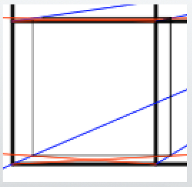
There is very little depth, but we will create the cubes within this narrow depth.
Note: Because this area is close to the horizon line, the depth appears compressed.
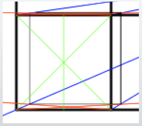
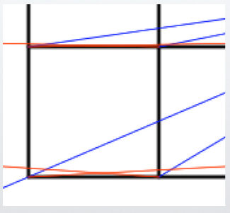
Next, divide this cube into two parts.
You can use either the diagonal lines or a ruler.
Note: Since there are no converging lines here, you can divide it using a ruler.
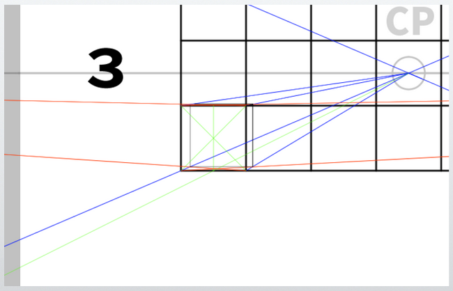
From the dividing lines, draw lines extending toward the CP (the vanishing point, or VP, in one-point perspective),
and then continue these lines extending in the opposite direction as well.
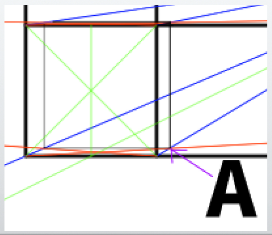
Call this corner of the cube point A.
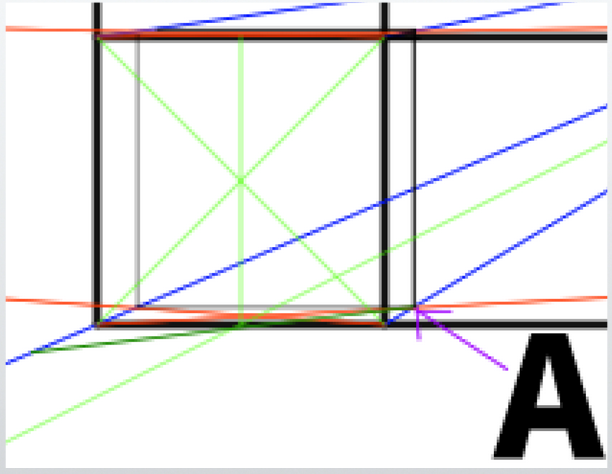
From point A, draw a line extending in the direction that passes through the dividing line you drew earlier.
This line should pass through the position that bisects the cube.
This method is a basic technique commonly used when dividing cubes.
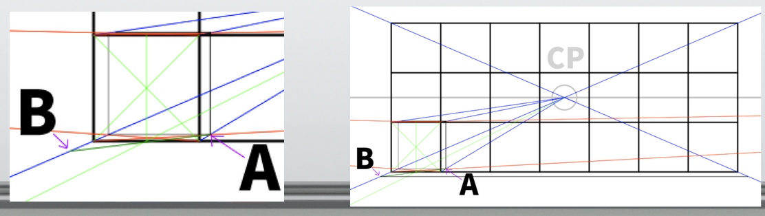
Call the point where the depth line (blue line) intersects the other line point B.
From point B, draw a horizontal line extending to the right.
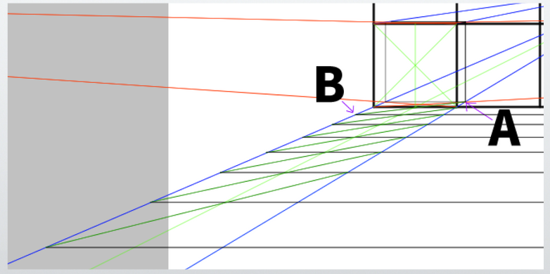
Repeat the same process.
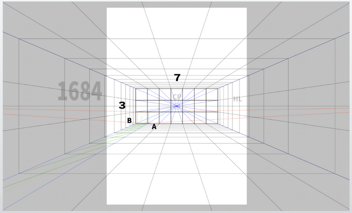
Here is the final result after drawing all the lines.
Draw the lines within a range that fits inside the canvas.
Next, use these grids as a reference to extend lines up, down, left, and right.
Since we are not doing actual architectural drafting, there is no need to be overly precise.
(I personally think the lines are drawn quite roughly.)
If this were a true grid, the lines should get thinner and lighter as they go deeper into the distance.
However, for this video, we prioritize visibility over strict accuracy.
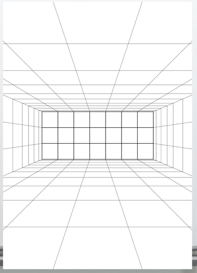
Here is a simplified version.
It is important to note that the floor should originally have a depth of 9 squares (however, the drawing shows 10 squares).
For tips on fitting the floor into 9 squares, see the final column.
The detailed rules have not been examined.
If it becomes clear at the stage of drawing only the floor that it does not fit into 9 squares, a simple solution is to redraw the back wall slightly larger.
Placing the blackboard, teacher’s podium, windows, and columns
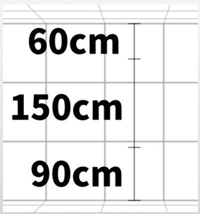
The blackboard is assumed to be 1.5 meters (about 4 feet 11 inches) tall and 4 meters (about 13 feet 1 inch) wide.
It is installed with a 60-centimeter (about 2 feet) gap above and a 90-centimeter (about 3 feet) gap below.
At 60 centimeters (about 2 feet) or 90 centimeters (about 3 feet), it is often quicker to measure directly with a ruler when working analog.
There is a geometric method to accurately divide the grid into 10 equal parts, but it is complicated.
As a simpler approximation, dividing into 4 parts is easier.
Also, instead of sticking strictly to 60 cm and 90 cm, it might be better to compromise with 50 cm (about 1 foot 8 inches) and 100 cm (about 3 feet 3 inches).
This secures the space for the blackboard.
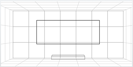
Next, all that remains is to research the dimensions of the teacher’s podium, windows, and columns, and then draw them.
For example, assume the teacher’s podium measures 200 cm (about 6 feet 7 inches) wide × 100 cm (about 3 feet 3 inches) deep × 20 cm (about 7 inches) high.
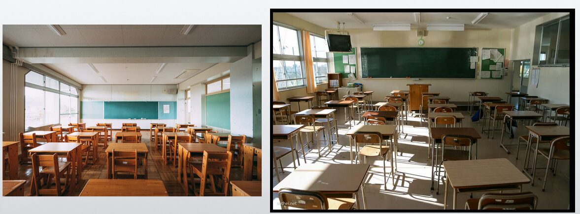
I searched for various free images of classrooms.
Windows are not usually located too low.
For simplicity, we will set the bottom of the windows at 1 meter (about 3 feet 3 inches) from the floor.
Windows are often divided into upper and lower sections, with about a 10-centimeter (about 4 inches) gap between them.
Also, assume there is a large column located roughly halfway across the room — around 4.5 meters (about 14 feet 9 inches) from one side.
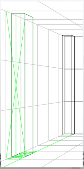
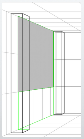
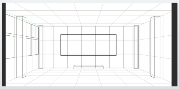
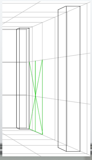
First, place the pillars.
By dividing the grid with diagonal lines, they were roughly positioned.
The pillar at the back is 3 meters (about 9 feet 10 inches) tall, 30 centimeters (about 1 foot) wide, and 30 centimeters (about 1 foot) deep.
The pillar in the front (center of the room) is 3 meters (about 9 feet 10 inches) tall, 30 centimeters (about 1 foot) wide, and 60 centimeters (about 2 feet) deep.
When cleaned up, it looks like this.
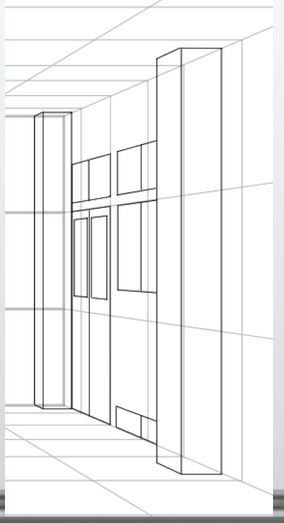
Next, we will place the windows.
Assuming the windows are about 1 meter (approximately 3 feet 3 inches) above the floor, this space will have several windows.
For now, we will assume there are a total of 8 windows.
They will be installed two windows vertically in each set.
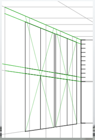
I roughly sketched them.
Of course, details like painting the glass or adding locks would be drawn later, but those are omitted this time.
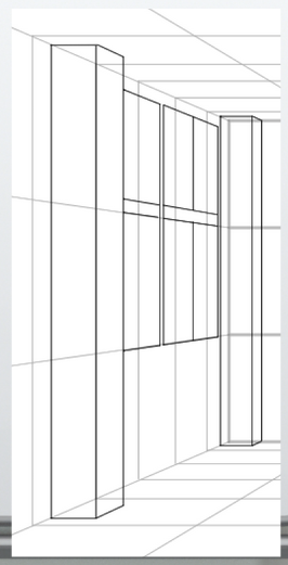
Originally, the windows would be partly hidden behind the pillars, so that area needs to be corrected.
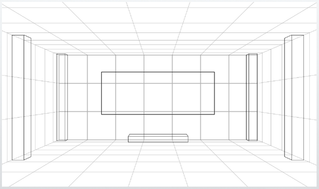
The overall image looks like this.
By measuring and drawing smaller items such as fluorescent lights, desks, and chairs in the same way, the drawing will be complete.
This time, however, the purpose is only to create the basic framework (grid room), so these details are omitted.
Finally, I added a door.
The height is 2 meters (approximately 6 feet 6.7 inches), and the width is about the same as the windows, around 1.7 meters (approximately 5 feet 6.9 inches).
Since the pillars are 30 centimeters (approximately 11.8 inches) wide, the door’s width fits nicely at the position of two grid squares, making it easy to understand.
Drawing the door creates an image like this.
I also added some windows and other details casually.
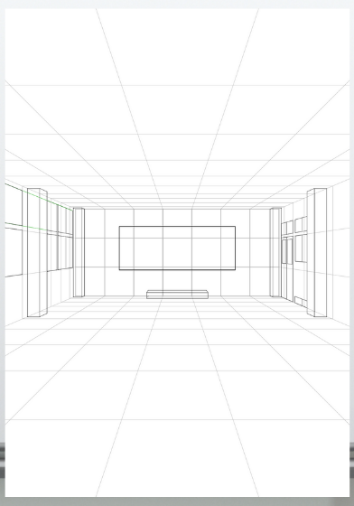
Here is the completed overall layout.
【Column】Imagining Classroom Perspective in 3D
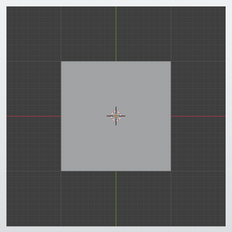
Assume that this top-down floor plan represents 1 square meter per grid.
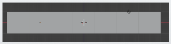
Duplicate the floor plan and make seven copies.
This makes the total width 7 meters (about 23 feet).
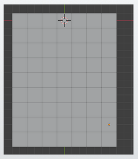
Increase the depth to 9 meters (about 29 feet 6 inches).
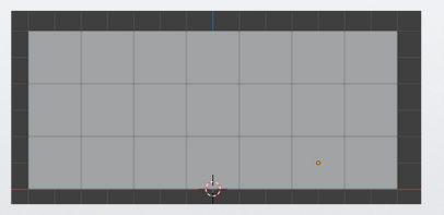
Create the walls with a height of 3 meters (about 9 feet 10 inches).
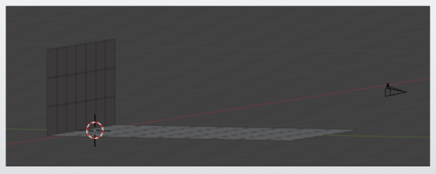
Place the camera at approximately 1.5 meters (about 4 feet 11 inches) in height.
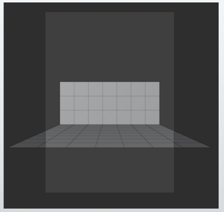
The view from the camera looks like this.
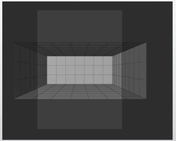
By constructing the remaining walls, the scene looks like this.
By adjusting the screen and grids to match the current composition, the scene looks like this.
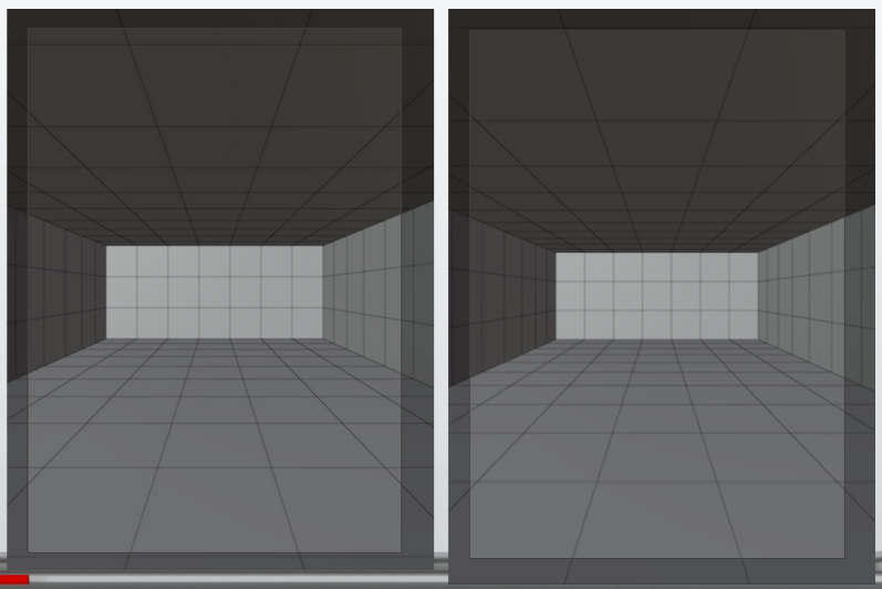
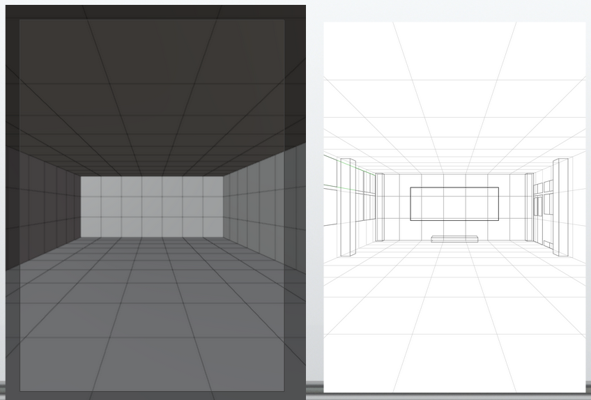
It is clear that in order for the classroom depth to fit within 9 grids instead of 10, the back wall needs to be about this size (the ratio between the side wall and back wall).
The left shows the case where the depth fits within 9 grids. In other words, the back wall needs to be drawn slightly larger.
If it is this size or larger, the depth will not exceed 10 grids in the view.
Next plan
The next session will probably be drawing the classroom using two-point perspective.
References
Books that are easy for beginners to understand
David Chelsea「Extreme Perspective! For Artists: Learn the Secrets of Curvilinear, Cylindrical, Fisheye, Isometric, and Other Amazing Drawing Systems that Will Make Your Drawings Pop Off the Page 」
The book contains many illustrations and is easy to understand. It also explains basic perspective terminology and provides a simple explanation of how to use perspective. However, it is important to note that the book focuses on ‘illustration (manga)’ rather than architectural perspective.
It is suitable as the first book to pick up for learning the basics of perspective in general.
Robbie Lee「Perspective Made Easy: A Step-by-Step Guide」
Robbie Lee「Perspective Made Easy: A Step-by-Step Guide」
This is a suitable book to pick up as the first one for learning the basics of perspective in general.
I found it to be simpler and more detailed than ‘Perspective! Learn Perspective Through Manga.’ Therefore, I especially recommend this book to beginners as their first read.
Scott Robertson「How to Draw: drawing and sketching objects and environments from your imagination」
Scott Robertson「How to Draw: drawing and sketching objects and environments from your imagination」
A book specialized in drawing, particularly focused on line art. Though somewhat complex, it provides a broad and in-depth explanation.
About the Japanese version of this article
This article is a translation of an article written in [https://souzoulog.com/2025/05/26/basic-of-perspective-9/]. For detailed references, please refer to this link.


Comments